Radome Measurement Systems

Radome Measurement Systems

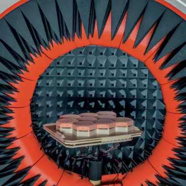
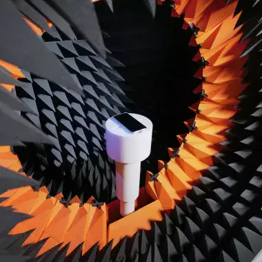
Radome measurement systems require exceptional repeatability and accuracy to detect small shifts in an antenna radiation pattern caused by the introduction of a radome. The load of the radome must not cause mechanical deflection, and the entire radome must consider the Device Under Test (DUT) within the quiet zone to accurately detect potential distortions.

MVG’s radome measurement systems address these critical challenges by offering fast, reliable, and highly accurate measurement facilities.

参考文献:

  • Radome measurement system

MEASUREMENT CAPABILITIES

  • Antenna Electrical Boresight (AEB)
  • Boresight Shift Error and Slope (BSES)
  • Transmission loss / efficiency
  • Transmission phase
  • Pattern degradation: sidelobes levels and beamwidth
  • Image lobe level and location
  • Cable loss and port balancing calibration

FREQUENCY BANDS

  • Up to 110 GHz

MEASUREMENT WITH GIMBAL

  • Gimbal based conical coverage scan of ± 60 deg, both in azimuth and elevation

POSITION ACCURACY

  • ± 0.1 mrad

PROPOSED CONFIGURATION

  • Motorized downrange slide
  • Radome azimuth / elevation positioner
  • Upper slide
  • Roll positioner
  • Gimbal roll positioner
  • Gimbal to radome insertion depth adjustment
  • Gimbal azimuth / elevation positioner
  • Scissor lift
  • Overhead crane
与我们的虚拟代理聊天