EMC Emissions testing is often considered the pinnacle of EMC testing in terms of how critical it is in getting a product certified for market. Virtually every region in the world has radiated emissions limits standards, with some wide variation depending on the application and where the equipment is intended to be used. Either way, radiated and conducted emissions testing is necessary for most major markets, and usually the test that is failed the most. This blog discusses EMC emissions, radiated emissions testing, and conducted emissions testing in hope of providing some insights to users on how best to prepare their products and processes for passing emissions testings.
EMC Emissions
Every electrical and electronic product produces electromagnetic emissions, both radiated and conducted (if another conductive structure is in close enough proximity). Radiated emissions can occur from any non-DC signal stimulating a significantly long conductor, which then is acting as an antenna transducing conducted electrical signals into EM signals, or radiated emissions. These emissions can be from the switching of a switch-power supply, digital circuitry, AC power being carried through a device, any signal generators, such as an oscillator/resonator, etc. Conducted emissions are different from radiated emissions, and instead of being transduced to EM energy and radiated, they are conducted into nearby cabling, typically the power supply cord or communication cords.
Radiated Emissions Testing
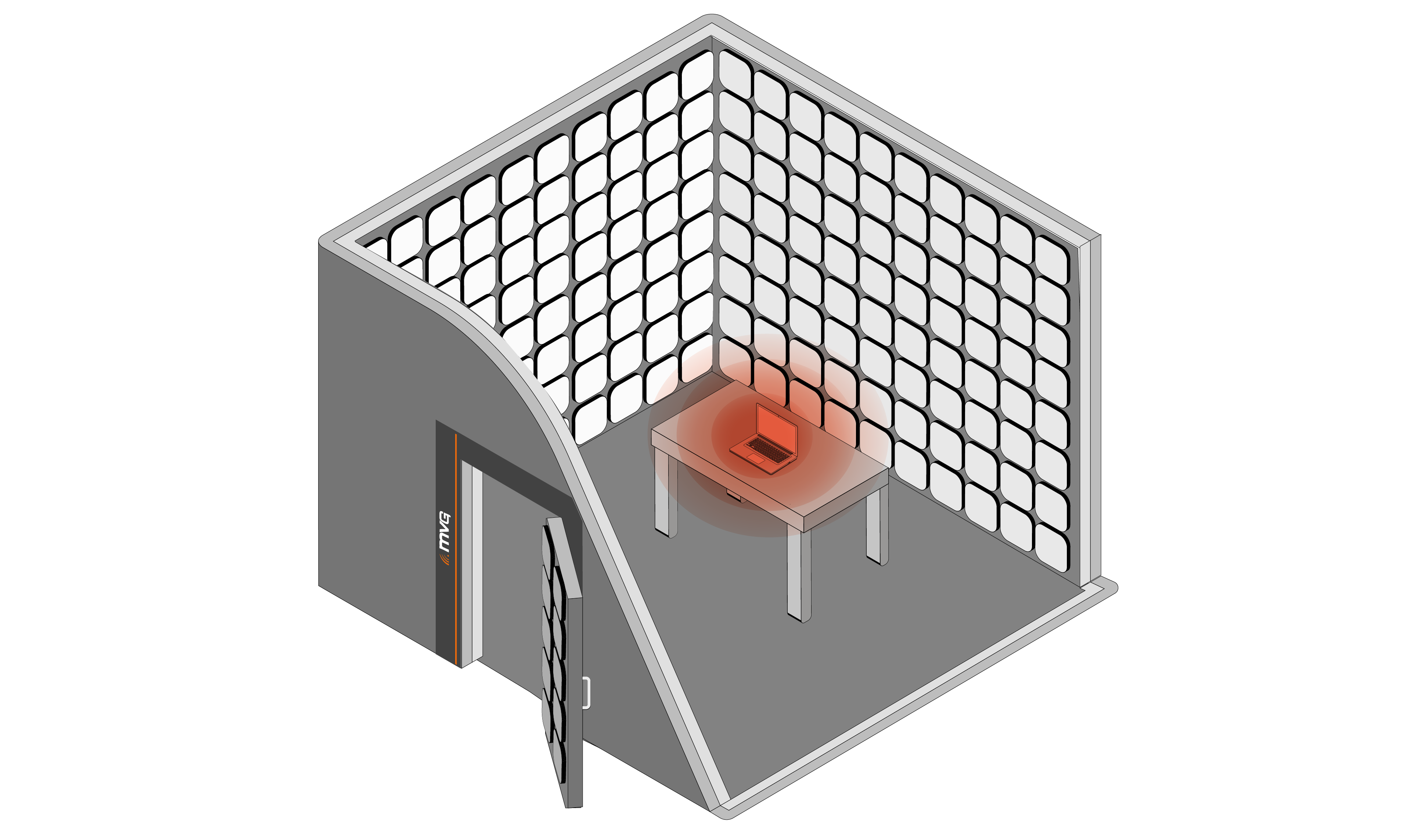
Given the nature of capturing radiated emissions in a consistent, accurate, and reliable way, radiated emissions testing is performed in well controlled environments, either in semi-anechoic chambers with reflective base plates or in open area test sites (OATS). There are some other options, but these are the most popular choices, as they are the most widely accepted and well established methods, with semi-anechoic chambers being the most common and accessible. Radiated emissions testing done in a semi-anechoic chamber involves the EUT being placed on a central turn-table that is rotated to present all angles of the EUT toward a measuring antenna that is capturing both openly radiated and reflected radiation from the EUT. This is done as some emissions from EUT’s can be rather directional and don’t evenly radiate from the emitter.
The radiated emissions test antenna is connected to test apparatus that are capable of sweeping across the regulated frequency range and capturing energy and storing the reading of the amount of radiated energy emitted at each critical frequency. Once an entire EUT is scanned, the radiated emissions report includes a strength of the radiated field across the critical frequencies, and this is weighed against the radiated emission limits in whatever region the testing is being performed to.
The exact radiated emissions limits vary based on region, as well as application. The highest frequency measured tends to be a product of the highest clock frequency in the design according to the FCC, but other applications or product types have fixed measurement frequencies. Certain applications, such as military, aerospace, space, and automotive, often have their own set of requirements for radiated emissions testing and their own stringent limits that must be met. These are often in a different set of EMC standards than those established by the FCC in the United States and CE for the European markets.
Conducted Emissions Testing
It is inevitable that some EM energy will be conducted into nearby cabling, especially if that cabling is directly attached to an electrical/electronic device, such as the DC power supply cord. Conducted emissions testing is used to ensure that the amount of interfering energy conducted back to the power supply is within specified limits, typically measured from 150 kHz to 30 MHz. Otherwise, excessive interference conducted to a power supply could cause aberrant behavior, including radiated emissions that are beyond regulated limits.
With conducted emissions testing, line impedance stabilization network (LISN) devices, sometimes referred to as artificial networks (ANs) or artificial mains networks (AMN). LISNs connect between a test device (EUT) and the power supply, and have an RF port that connects to a spectrum analyzer, often with some type of transient surge protection/limitation to prevent damage to the spectrum analyzer. Essentially, the LISN presents a known impedance and isolates the unwanted RF signals from the power source, while also presenting the RF signals from the EUT to a measurement device.
These conducted emissions are measured against various standards, like radiated emissions, the accepted limits often depend on the exact region, application, and product type. Conducted emissions failures are very common, often because of a power supply, even pre-certified power supplies, resulting in failures. This can be because of the difference between how the pre-certified power supply was tested and how your device operates, manufacturing variations, or issues with the original testing. This is why power supply selection is critical for conducted emissions testing, and it may be wise to have several different power supplies available for conducted emissions testing to increase a chance of a pass.
Topic overview

